Club Article
Dedicated page to highlight a long, photo rich article done by an IPMS Salisbury Club member. This will change periodically but two articles will be here for at least a month to allow anyone tackling a similar build to gain use of the photos and notes. The newest Article will always be at the page top so scroll down for prior article if you have been referencing that.
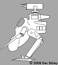
Article 1 by: Dec 'SIBO' Sibley Ma.K LUNADIVER 'STINGRAY' in 1/35 scale by Hasegawa.

I really like Ma.k and consider myself lucky to have become first acquainted with SF3D, the original form of Ma.k as a model making teenager. However I’m not fanatical about Ma.k. There are some designs that don’t attract me and therefore have never been on my “to build” list. Surprisingly, considering this article, the LUNADIVER is one of the Ma.k vehicles that never appealed to me, I love the idea of Armoured fighting suits, and the Walkers and IA vehicles are equally imaginative yet quite obvious in what they represent. When displaying the Ma.k fighting suits for example, observers with no real knowledge of Ma.k or Sci-fi modelling in general recognise what an AFS is; a man in a powered fighting suit. The LUNADIVER is a different matter. Designed as a single seat fighter and ground attack craft for use on the moon it is certainly a unique shape fitting its call sign “Stingray”. But it lacks wings or landing legs or even a cockpit windscreen, all the things that help identify a ship to the viewer and why so many famous film spaceships have these features.
So when I obtained the massive box containing the LUNADIVER STINGRAY kit I wasn’t immediately hooked, I was however very impressed with how HASEGAWA have put this model together. I have built a couple of HASEGAWA’s aircraft kits before and have always been impressed with the fit of parts and general presentation of the subject. I anticipated the same with this model and overall was not disappointed but the fit of parts was at times an issue which I have highlighted during the build article.
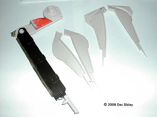
The box is big and packaged beautifully still including the famous SF3D coloured marking sheets. Two sets of very clear instructions are included with the bagged sprues one for the Stingray and one for the two miniature SAFS. There is a lot of plastic in the box, the majority in white with a single sprue (K) in dark grey for the cockpit seat and two crew figures. Also included are two sprues containing parts for a large display stand which is a must for a model that has no landing gear (L and Z) and a set of Poly caps.

The instructions are very clear and build is swift. Step one is refreshing, I was handling large components from the start and the size of the craft is apparent straight away. The body parts are big and very curvaceous. The cockpit is constructed early on with only 3 parts but they exhibit fine detail of wire and tubing. If the cockpit hatch is left open then the provided detail is adequate. A bigger hatch is also provided but the instructions show it glued into place so the requirement of a separate piece is not obvious, it does however allow extra interior to be viewed and with that in mind I decided to add to the basic cockpit seat. Armoured side panels, a tubular frame work with sprung seat mounts, radio boxes and a radiator were all added. I kept assembling the body around the added detail to ensure the hatches still fitted and apart from the radiator thought I’d achieved that aim, unfortunately later once the body was glued together properly the large hatch was not able to fit exactly, my fault for trying to make the tolerance to tight. If assembled as intended the kit would have no problems. I was not bothered by the fit problem as I’d already decided that the hatches would be removed to allow full view of the interior. It also allowed the fitting of the large radiator which I liked despite it being a bit too big. All the extra detail parts came from the chassis of a 1/24 Shelby Cobra cut and rearranged. The inside skin of the body components benefit from a coat of black paint to add depth to the interior and I also added some detail to the inner walls. The tail boom is hollow and fits with strong locating lugs. I added a set of wire strands to give the make the boom busy.

Immediately the build began I noticed that the attachment points of each part to the sprues were quite large and offset. I believe this is to ensure that the attachment stub does not mark the part in any way when being removed but I found it increased the work of removal. The biggest problem being caused by the stub looking very similar to the locating pins as it was off set. Also the stubs were often very close to raised details that meant a quick swipe with a sharp blade was no possible needing a number of chisel style cuts to remove the offending stub. This is not really much of a problem but throughout the course of the build does add a little extra time.
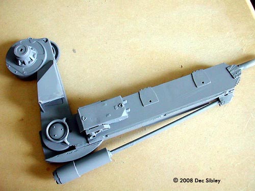
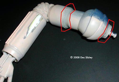
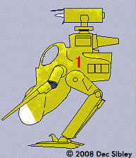
The bottom fuselage mounts the rail gun and parts are need to make the recessed mounting point. This area was the first to display alignment problems made obvious by the moulded pipe work that is a feature of the LUNADIVER. I elected to line up the pipe work and deal with any other joints after the glue had set as I figured the pipe work would be the harder of the two to fix. The joints shown run through the lower lobes that mount the engines and along the back of the ship. Join A in the picture below was filled and sanded, while B was left and treated as a panel. I dealt with the joints by rubbing Squadron white putty into the join line, the white would help the subsequent painting as it would blend in with the unpainted plastic, while darker filler would show through unless a number of primer coats were applied. The poor joints also extended around the rear up to where the tail extends from the body. While not major, these joint lines broke the smooth flow of the LUNADIVER’s form so need to be removed. To prevent dust from sanding entering the many openings of the body and ruining the already painted cockpit masking is required and to minimise dust wet and dry paper was used instead of sandpaper. Wet tissue was used to block openings and Kitchen foil with masking tape for the bigger area, the foil conforming easily and keeping its shape. A small square of wet and dry paper was used at a time, run under the tap before sanding begins so that the dust becomes a slurry that is easy to control and wipe away. The wet and dry paper clogs often but running it under the tap clears it quickly. When the paper becomes too soft, the grit starts to come away from the backing paper, simply use a fresh piece. A hooked scalpel blade redefines the pipe work where is has been accidentally sanded. Joint B is made into a feature using some of the many extra rivets that HASEGAWA thoughtfully include on Sprue J. These are also called out in the instructions to allow the builder to detail the body by adding raised rivets instead of the flush ones that are moulded in place. Filling and sanding was also done on parts C2,C3, C17 and 18, the Reactor pods. These rear facing curved ends need to be smooth and while the joints are not too bad extra effort will be worthwhile as this area is prominent on the finish model.


The instructions continually remind the builder to follow the correct order of assembly and for the most part this is a sensible as the components are such awkward shapes. I deviated from this in only two places. The tail boom was glued to the lower hull first rather than the top as instructed. This allowed me to add the detail to the boom and wire it under the cockpit tub. Step 6 would have you add parts A6 and A5, the car door shaped shield or airfoils. To save from damage and aid painting and decaling of the main hull I added these at the very end. I felt the armour shields looked too much like the original donor part so masked one to show it field repaired with a panel of unpainted metal that had tarnished. Navigation lights were added from scrap clear sprue into the shield recesses
All the Poly cap mounts work well and gave the Rail gun full movement as well some degree of pivot to the engine bells. The engines are “Plasma Rocket Motors” according to step 7, and have ‘Mr Color’ painting references. Unfortunately the numbers are not in the paint chart, only 9 colours are named. At first I was going to paint the engine bells metallic colours as per a normal rocket but noted the box art showed them the same colour as the main hull. Having no idea of the colour of plasma engines I went along with this and used ‘Lifecolor’ white oxide to colour the black interior with Burnt brown over the top. These colours are from the ‘Lifecolor’ TENESCROM range and give a range of useful washes that can be used in different ways to give depth to details or subtly change basic colours. I used the Oil wash with a little Burnt brown to change the engines colour a little from the main body to show the effect of heat and different materials. Salt was applied wet to the black painted bells in a random pattern and left to dry in place before the green overcoat was applied. Once dry it was washed and then lightly sanded to restore smoothness and give a worn appearance.
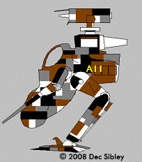
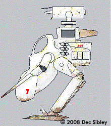
The body after preparation was sprayed in acrylic Ice Green, an unusual pastel colour. I just picked this colour at random as I was a bit fed up with greys and whites, the colours I’ve been using a lot of recently. Once applied it looked great and proved a great back ground colour for the Digital Cam decals I had created.

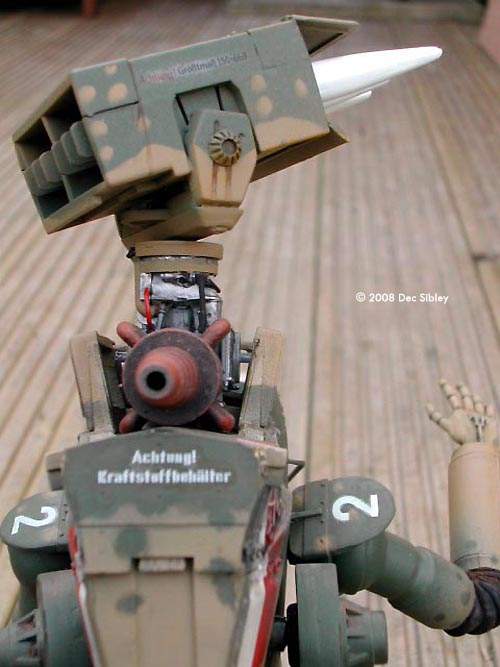
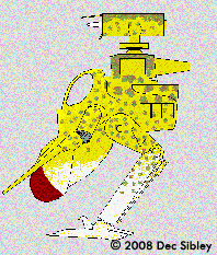
Despite the change from grey I still aimed to use the marking guide for “7th Yeomanry Regiment, 2nd Ground Attack Company – Flt. Lt Giotto Uffizi” so over the base colour dark red was applied as per the guide. I made a small mistake as I matched the colour to the colour card, I should have checked the decal sheet as the numbers which were shown on the card were in fact lighter and more vibrant. This can be seen in the final pictures though it does not detract at all. I masked off the tail and nose, and also sprayed the sensor head separately. Wear and tear was added with ‘Games Workshop’ Dwarf Flesh which was a touch lighter than the red I’d used, some scratches having dark grey as exposed metal. Intentionally weathering was kept light as I’d assume there would be less wearing effects in space. I did add impact spots to the face of the Radar ( E4) that was done in tan as such a flat area is bound to pick up marks from micro space debris as the LUNADIVER flies through the lunar atmosphere. The shields ( A5 and A6) were also sprayed red but the Railgun was left plain with just the Digicam applied. Most will added the extended air tanks (J7 and J8) as they really add to the Ma.k look but as I was modeling the craft as if in maintenance used optional J9 instead. Note the shape of B23 too as it conforms to the curves of the airframe but only if placed exactly.
The final finish of the LUNADIVER was the hook that overcame my apathy toward this kit. Once I’d decided I’d give it a digital camouflage scheme I couldn’t wait to get to grips with it and find a way to apply the scheme. My references covered a wide range of real world examples, Chinese tanks in bold digi cam, Aircraft in digital style swathes, real US marine fatigues as well as video game renditions. I wanted a close repeating camouflage so looked at the tight pattern of the US fatigues and dismissed the larger vehicle cam schemes. Any printed material will have a repeat patter but comparison of Digicam with normal Disruptive Pattern Material (DPM) cloth showed a far large amount of material had to be viewed before the pattern began to repeat. This feature makes Digicam appear more random than previous style camouflage uniforms. I thought I could save myself time by applying the scheme in bands like a WW1 Lozenge pattern as seen on German aircraft. This was flawed partly as the repeat undermined the camouflaging affect of the digital scheme and partly due to the complex curves of the LUNADIVER body. In the end I resorted to individually cutting a piece to fit every area of the body, completely wrapping the craft in decals. The digicam took more than 7 hours alone and once satisfied a second round of decaling with the markings and warning stencils began. Using 'Crafty Computer Paper’s' Laser Water-slide Decal sheet. I produced my own Digtal scheme and printed it onto 2 A4 sheets of decal paper using a Inkjet printer. The clear areas allowing the base coat of the model to shine though. Before decaling an area at a time was painted with “Klear” Floor varnish to give the smoothest surface then each decal applied. Once dabbed dry Revell decal soft was painted on to ensure maximum conformity. This has for the most part worked with only a few spots of ‘Silvering’ appearing,I used judicious paint chips to cover the ‘silvering’ rather than reapply the offending decal.


While those few sentences make the process sound simple in truth I was continuously frustrated. As the ‘Klear’ polish dried it became very sticky and I was constantly removing brush hairs, flies and dry flakes of polish. My worst mistake was leaving the brush that was applying the polish to dry slightly, I hadn’t realized that the polish had set inside the bristles and once I started the process again dried polish was flaking off onto the surface I was trying to make smooth. As ‘Klear’ is water soluble dipping the tip into water should stop the polish drying onto the brush, I’ll remember that next time.


Once the huge task of decaling was complete the final kit parts were added and detail painting carried out including the red outline of the removed panel. ‘Little lense’ 2mm dark yellow lenses were added to the Optical Seeker. The stand is large and fits into the rear of the craft on a spigot that allows it to be slid off. Part B10 covers the hole when the stand is removed. I did not paint my stand as I intend to display the LUNADIVER in a manner that will not require the stand, but for most the stand is as important as the undercarriage on a Spitfire to display the model properly on a shelf.

In summery I have to admit, this was a pleasure to build.It is a quality kit but needs the full range of builders’ skills to rectify the small mold lines, seams and gaps that do feature. However while it does require filer and sanding to look its best it is not a poor kit and goes together well thanks to a great set of instructions, well planned parts assembly and few intricate assemblies. A builder wanting more finesse and with time may decide to remove all the molded pipe work and replace it with soft solder but other than that any further work is not necessary.

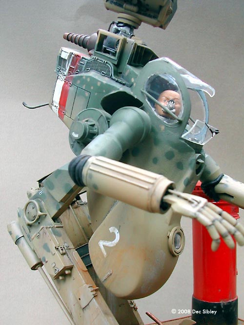
Article 2 by Dec 'SIBO' Sibley Scratchbuilt S.P.K.A ZORNIG MUTTER in 1/12 scale.
Initiated by an on line challenge made up of mostly US forum members on Starship Modeler, a sci-fi orientated modelling site this is the build story of my 'Walker Armoured Fighting suit' in 1/12 scale. The challenge was to send each other a box of left over kit parts and scrap items and build something unique with the contents.
Due to commitments I didn't start till September 2004 and finished well past the official dead line. Thus it was that mid-way into September I finally opened my Box and was met with a couple of surprises.
The first surprise was that a printer cartridge had leaked yellow ink over everything. Had I noticed straight away this might not have been a problem, but as the lights were on dim and with the kids helping rummage it wasn't until the call for bedtime revealed their hands stained yellow not to mention my trousers and worst of all….. THE CARPET. First delay to building as I was well and truly in the wife's bad books and a weeks worth of chores round the house meant no model making for me. At least this time at the sink could be spent dreaming up some design ideas from the parts.
The Parts in the Box
This was to be the second surprise, as I'd expected to receive a lot of jet airplane wings and body parts, as in general I had seen a lot of these type parts on the pre-build photos of the other boxes shown on the forum. At first I thought “great a really full box” but slowly worry set in. No plastic sheet? Not many big parts. A lot of sprue, but seeming to not have much on them? Wings from a WW1 biplane? Oh dear. This is what I got:
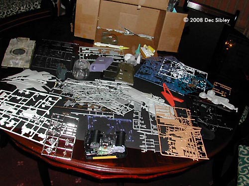
- 2 x 1:35 scale M60 tank hulls joined.
- sawn off AH6 Helicopter body.
- 3 x sprue of car parts.
- 1:35 WW2 German truck body.
- Bi-plane wings and bits.
- Gundam / Manga sprues.
- 2 x top, 1 base of AFV's 1:48 scale.
- Xisors ship's wing parts x 4
- Aircraft sprues.
- Disposable camera.
- hard plastic baby-bottle nipple package.
- Odd plastic lids and tap adapter
- Home made moulded casts.
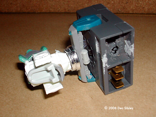
- large electrical component.
That first night I felt no inspiration. I set aside the biplane wings and parts to build a retro heavy fighter. (This would only be a small number of the parts from the box but at least I'd be doing something.) But faced with the joined M60 hulls and the cut down heli body, no wings or wheels, and no obvious jumping of point, I was stumped but I was about to make the first important step that goes with scratchbuilding.
I think it was Randy Cooper, way back in my youth, who in an article in Fine Scale Modeler who said “ There's nothing worse than seeing a Panzer III in space” and this quote sums up the difficult thing that goes with scratchbuilding. Incorporating parts into a model design so that all you are finished with is a coherent, believable space ship and not a set of spares put together in a spaceship shape. There are loads of German AFV parts in the hull of the Millennium Falcon, for instance, but their use and adaptation means they are not readily apparent. From my box of parts all I could see was M60 tank hulls and whichever way I arranged parts on it, it looked the same. “ US ARMY in Space”. That was not the thing I wanted, and although I like hover tanks, building one around the M60 was not a realistic idea.
The AH6 Little bird Helicopter body was knocking at my mind. I love the Sf3D range and realised that the PKA Ausf H by Kow was based on a AH6 Body. The one from my box was a much larger scale and I'd be hard pushed to get anything like legs and arms from the spares, yet…I was getting the bug and this would allow me to make the first step I'd mentioned in convincing scratch builds:- Seeing through the parts.
I wanted to do a model that would be identifiable with the Sf3D universe; the helibody gave me a link now I needed to overcome the random parts in the box. To see through the parts I took the M60 hulls and drew around lumps and along lines, dividing it up into chunks, imagining what each chunk looked like, this exercise allowed me to forget it was a tank hull and I began to see the hulls as just a series of parts. Now I was on a roll.
The M60 gave me an engine, The Virago's wings were halved and attatched to the AH6, the blue Gundam parts would provide arms. Upper legs would be the grey “chicken drum stick” parts - Only 3 of them in the box- blast. I'd need to work out how to box the rear of the drumstick-shaped parts later. Clever cutting of the black tank chassis gave me two sides of a lower leg assembly, also two rotor blades and some desperately needed flat plastic. The feet? Well I'll think about that later too.
So here was the vision so far: an “Armoured fighting suit prototype” with rotors for VTOL. Actually this title and design would change, but as that night drew to a close at 0330hrs in the morning I was actually feeling excited about my creation. How very sad is that!
Next Day
I was having a field day on sticking stuff together and having it set real firm with Revell Contacta. I'd taken the Hump from the M60 engine decks and part of the grills, removed most of the track boards but kept the hull sides. 2 of these stuck together and tapered down to give angled sides. The 4 sets of wings from “Shadow of the Empire” villain Prince Xisor's space ship were halved and increased the bulk of the body area .
The angled rear allowed fitting of an intake grill from an Italeri “stealth plane” which almost matched perfectly. The area behind would be the engine and rotor head. Sprue was used as strengthening rods and this engine / body assembly was fitted to the “rear” of the model, the heli's underside. I get side tracked easily and noticed some interesting parts from a small scale car, the radiator had some moulded fan detail that I'd like to use, so with so much still to do I instead started to work on the rotor head. The radiator was halved to put a fan each side. Other engine parts mounted on their end gave a mount for the blades and a nice green tap adaptor would be the exhaust.
Now came the first problems. The plastic tap piece would not stick - wrong type of plastic. I'll come back to that later. …And something didn't look right on the rotor. The blades looked far too small. Change of vehicle, I'll have a radar dish made from the front of the camera instead…
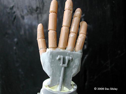
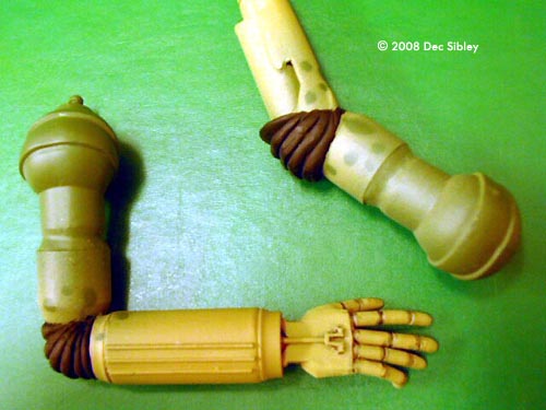
The rest of the wings are used as feet and detailed below. Sprue spacers gave the required strength to the assembly. Arms were produced from Gundam parts and a resin cylinder to which a hand was added (originally from helicopter skids for fingers.) the left arm ends in a long barrelled weapon. A weapons launcher mount using a large computer component was created for the top. With the cockpit in good but rough shape I could move on to the legs.
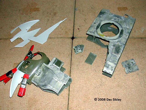
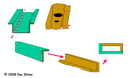
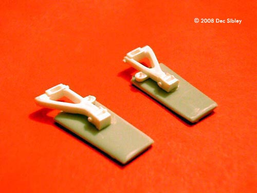
Each leg was created from a side wall from an unknown AFV hull, which was then coupled to a similar-shaped side wall from the M60 hull top as shown in Diagram 1. This construction not only made best use of materials and time but meant it was far stronger than using 4 individual faces.
It should be noted a lot of time was spent on deciding the leg lay out both in position on the body and direction of joints. I went for the "chicken leg" style with the joint rear rather than have a knee. This allowed the body to be visible and the arms a free range of movement.
A dry fit of the parts showed things going well, but the number of parts plus filler brought the weight up more than I was happy with. There are two areas for concern. The hip joint would be under pressure and the ankles would be supporting all the weight as well as balancing the whole vehicle. By drilling right through the body and inserting a piece of thick sprue I thought the hips would be strong enough. Aircraft wheel halves would be gaiters to allow some twisting and space the legs away from the body for a wider stance.
The remaining parts of Prince Xisors ship's wings would be the feet, the large size hopefully allowing the model to stand. However I was not happy with the shape, being far too removed from the other style of SF3D walkers such as “KROTE”. A curved template was made and drawn onto the wings to allow them to be reshaped more in keeping with the look I wanted. Despite the size these feet did not help with supporting the model and leads me to my first cheat!
Using an idea often used to support white metal horses in military modelling, I glued some very thick sprue inside the box sections of the lower leg leaving about an inch protruding (wire pins are used on the horses). Using a suitable sized wooden base two angled holes where drilled and the sprues inserted at this angle. This was strong and allowed me to dry fit the complete body to prove it could support the weight, which it easily did. It also meant that I can build up the feet in situ, able to achieve the look I want with out having to worry if the ankle would be strong enough. I hope you'll forgive the use of the wooden base as it did not arrive in the “Box”.
With the vehicle now fleshed out it seemed logical to work on each section separately ... in no particular order.
- Finish the body work
- Fully clean up and detail the legs
- Completely build the feet
- Make new fingers for the hand
- Detail the cockpit
- Complete the Weapons launcher
The Weapon Launcher
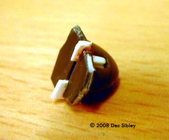
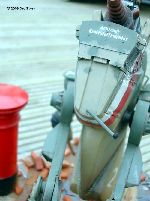
The weapon launcher turned out to be very easy to finish. I used a metal cutting disc and just reduced the metal contacts length. A redundant plastic name plate was cut to size and using putty bonded to the metal parts, with filler used to make the face flush. Once accurately marked, 4 missile locations holes where drilled for sprue attachment points so I can add the missiles after painting. One location was drilled out wider to reflect a fired missile. Happily this is now a sub assembly completed.
The Legs
I was unhappy with the bulk and detail being on the inside faces of the legs like big fat inner thighs. As this was moulded detail I felt hesitant about removing it. But to move forward with the project I had to address what I felt did not look right, so out came the razor saw. The fineness of the razor saw is great and allowed me to saw off the remaining turret collar and base to the stowage bin. As expected the detail was hollow so both putty and tube filler was required to fill the resulting holes. Even though the saw got right down close more sanding was needed to remove any traces on the inside leg. The semi circular turret collar parts can now be relocated to the knee joint and will allow mounting of the hydraulic pistons. These pistons are made from old resin cast offs that once the air bubbles are filled and the ends sanded down make nice chunky cylinders into which I drilled holes for long lengths of thinner sprue.
Airplane prop mounts decorate the top ends. These cylinders are pinned using sprue for strength onto the curved turret collars at the top end of the lower leg, giving a very functional look. With detail removed from the inside I now needed to add detail to the outer face of the legs. Stowage boxes gave the outer legs detail and I added sawn off air grills from a Marder AFV to jazz up the inner faces.
The drumstick-shaped thigh part of the leg now needed beefing up so rearward facing air scoops were added, each intake being made of 4 parts angled to fit the drumstick adding bulk in this area. To panel in the rear of the drumstick a template was made by pressing a small sheet of paper over the part and rubbing the side of a pencil over the edges of the plastic. This marked the paper in such a way as to allow me to cut out the shape and once tested transfer it to some of the now diminishing stock of flat pieces left from the tank hulls.
As I'd made so much progress with the legs my attention now drew to the feet. These would be two parts, the main foot pad and a smaller heel or back toe separately connected.
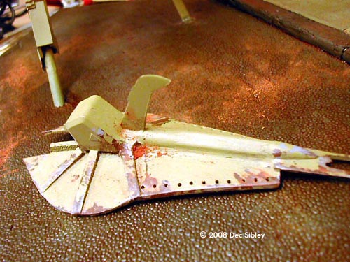
A small gear was taken from the camera (the one with the exposure numbers) and cut in to segments to add detail to the end of the leg. The rear toe was a flat made up from a piece of WW2 airplane tail wing. (The flap part was removed and added at right angles to the main foot to be a cable cutter as seen on US military helicopters). The ankle joint was raised with shoulder boxes from a small Gundam, and then lots of channels cut from a display stand and missile halves to create a raised piece the length of the foot. Once again some filler was needed to blend.
Looking for some ideas for design linkage to the SF3D universe I concentrated on the “Krote's” foot pad. The design is shaped totally different but has a rear toe also. I used some car suspension parts to mimic the attachment points of the toe and then copied the style of reinforcement of the foot by using strips from a German cargo truck. My initial fear that the feet looked bland compared to the rest of the SPKA was now disappearing.
Now came an annoying evening. As I lifted away the “Krote” box I knocked another model box from the shelf and it landed on the “ZORNIG MUTTER”, breaking the engine totally and snapping a finger on the newly designed hand. The heli skid fingers seemed to thin so digits had been made from sprue turned in my mini drill, a file used to mark joints. It took ages to find where the major piece had flown of to but once all the parts where collected together a good hour saw the engine rebuilt with only a few detail parts missing.
Now for a few days the model would have to sit waiting for a prime to see how the filling had gone and so the feet would set rock hard before sanding the reinforcing strips into a taper to match the “Krote's” style of feet. This time was not spent idly and using the simple PAINT programme on the works computer I knocked up a diagram that would aide me in some camouflage scheme ideas. I had begun to realise that access to the legs and feet would be limited as the parts were attached to the body and pinned onto the wooden base so painting would have to be a factor of construction before final assembly.
Colours & Markings - Interlude
Now for a few days the model would have to sit waiting for a prime to see how the filling had gone, and so the feet would set rock hard before sanding the reinforcing strips into a taper to match the “Krote's” style of feet. This time was not spent idly and using the simple PAINT programme on the works computer I knocked up a diagram that would aide me in some camouflage scheme ideas.
|
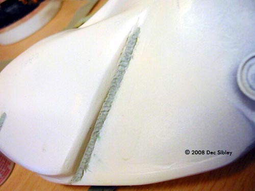
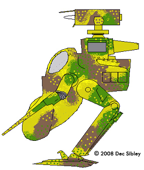
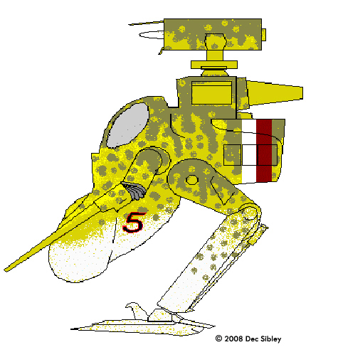
I had begun to realise that access to the legs and feet would be limited as the parts were attached to the body and pinned onto the wooden base so painting would have to be a factor of construction before final assembly. Diagram 2 shows a rough idea of how the Schwer PKA Luft Verteidigung " ZORNIG MUTTER " would look. I had some ideas for what I wanted but a modelling friend had suggested a couple of schemes too which had grown on me. A shot of primer on the legs and body revealed that they STILL needed more filling and sanding. To say I was sick of this would be an understatement, especially when the dead line was due. As a refreshing aside, my mind turned to colour schemes. I had wanted to try a BF109 scheme from early in WW2, as most of the Strahl forces adopt pseudo-German schemes and I liked the light base with darker uppers. A friend suggested an Afrika Corps scheme or the often-used Ambush scheme seen on late war Panthers and King Tigers. I mocked up the following on the computer: This simple colour scheme allows for really dramatic weathering, but I'd used yellows a lot in the last few models I'd made and wanted an Urban setting so decided against this idea. This camouflage scheme was used in the Cold War by British forces stationed in Berlin and was worn on Chieftains, FV432, Fox armoured cars and Land Rovers. Ideal for FIBUA, but not good for this model. Apart from being the “wrong side of the fence” more suited to the Sf3D Mercs', I felt the blocky colours would hide some of the detail of the model and as it's a scratch build I want (vainly?) the whole thing to be appreciated. I liked this one a lot as it had the lighter underside I'd got from the ME109 but with a yellow and olive green upper layer, far more traditional AFV colours. The red belly marking added colour. Just did this for fun with some kill marks, but really liked it and could go to town on the weathering. I think though that as my model is 1:12 scale I should go for a more complicated and interesting scheme though. This was my friend's other suggestion that I too had thought about, but felt had been seen too much on Sf3D models. When I coloured up the diagram though I must admit to thinking how great this one looked. This idea could make it to the final even though decided on the following design at this point in the build. I still wished to try the lightened lower legs and body, but increased the total amount of Olive Green down the top with some blotching more similar to the Ambush scheme. I have called it Dora because it's a little bit like the FW190 with banding for Reich defence. Well the hypothesising was fun but must get back to building Adapt, Adjust, Overcome Frustration at the lack of progress due to work and being away meant even more delay to the finish. I had so far achieved far more than I'd expected and had already reworked the legs so as not to compromise what I wanted to achieve, I couldn't bring myself to rush the final stages. Also I decided to re-evaluate the main body as I was totally fed up of trying to make the belly area smooth and crack free. A simple solution? Hide the problem! Instead of eliminating the difficult join and the weak area prone to cracking I made a feature of it by adding weld seams from thinly rolled “Milliput” textured with a pencil point. This strengthened and hid the join and actually enhanced the whole thing. I added some welds in other areas too carry on the theme.
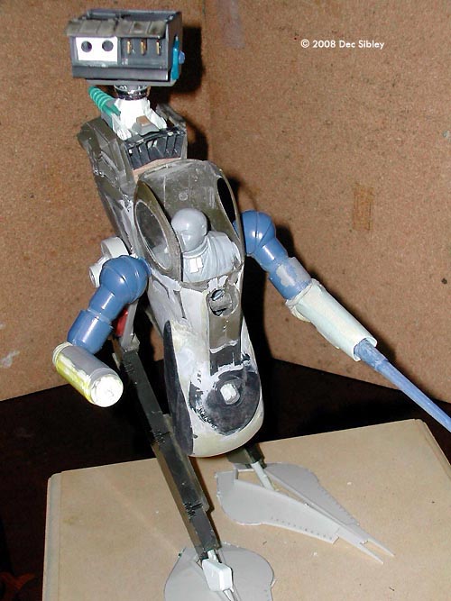
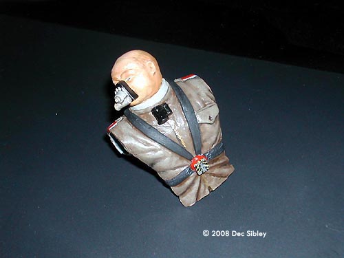
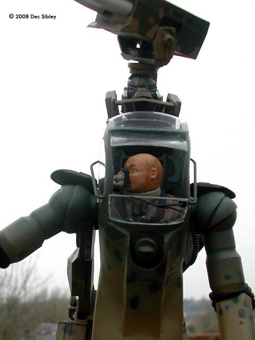
So after overcoming an area that had become a sticking point it was time to move on. I painted up the 1/12 scale pilot (not from the supplied 'Box' but did give a sense of scale, another cheat I'm afraid.), giving him a 4 point harness with quick release buckle and a paint job of brown leather jacket over a grey roll neck finished off with a not often modelled “ male pattern baldness” hair scheme, I suffer from it so why shouldn't my models? His respirator was painted black and white with Tamiya Smoke used to dull it down and add depth. The feet were tidied up; the supporting braces reduced in thickness down to a taper to match even more the “Krote” and primed to ensure the putty seams had blended in. The area behind the cockpit and in front of the engine intakes was still a mismatch of parts so a template was made from paper and a small set of wings cut to fill the gap. This was slightly too small but the gap made good with milliput blended with a wet brush. The side pieces of the same area where filled with Squadron green putty to fill them out and sanded to blend with the curves of the same area. As many of the Strahl Fighting suits had what looks like German motorcycle headlights I now endeavoured to make one that would keep the overall look. Using a prop spinner, and some scrap flat parts with a bit of filler a suitable item was successfully created.
Both arms were now also tided up; wipes of Milliput to smooth out some joints and thicken up the shoulder area. It was far too slim and needed to look able to have a 1:12 scale arm passing through it into the armoured sleeve. I decided to try out the paint scheme on the arms and using spray cans for speed tried the Blu-tack method. By masking of with blu-tac and then misting on the Desert Sand colour over Yellow Olive to have a softer mottle effect at the transition between colours.
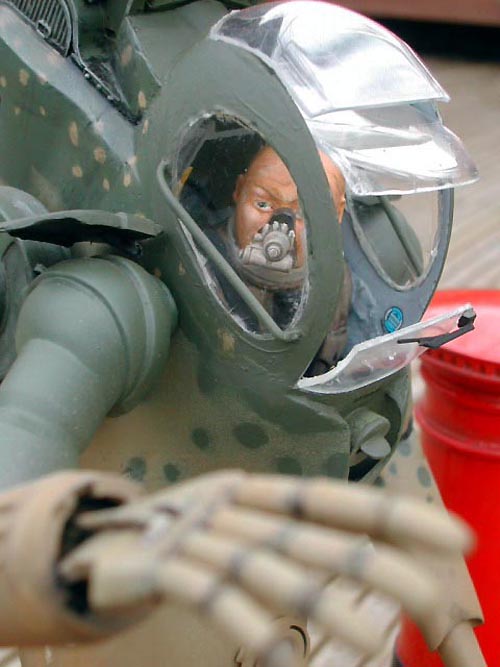
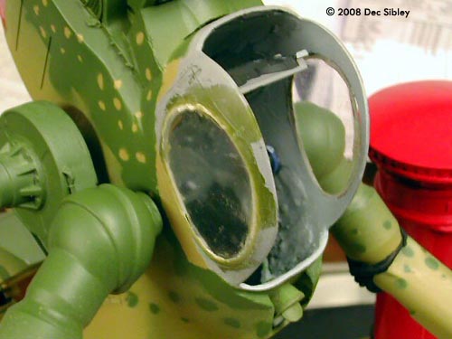
Glazing The keen eyed of you will note that the right hand side has been glazed from almost the start of the build. I had been worried about how well the clear plastic packaging would cut and glue so had tried out a method to see if I could cut curves. It worked so well that I had a window straight away so glued it in place but decided to try and keep the remaining windows as clear as possible and thus to do the rest at the end. The plastic was very brittle and did not take scoring with a knife at all well. Lateral pressure also caused it to craze so no snapping off scored lines. (A small amount of crazing is visible in certain light on the right window) In order to achieve the curved side windows the following route was taken. The clear plastic was offered up to the cockpit hole and using a pin a fine line scored into the clear surface. This was then gently gone over with a revolving drill bit in my Dremal. This deepened the fine line and as I was leaning the drill at an angle, gave a chamfered edge that would fit the reassess perfectly and allow a little bit of scope on movement to get best fit. Once I had a deep outline I then applied enough pressure for the drill to push through and then using the side of the bit “cut” around the shape slightly wide of my finished piece. The drill bit became so hot that it was infact melting its way around the window. Once released from the remaining clear piece all I had to do was rub away the melted part up to the weaker line leaving an oval window that was tided up with a very sharp blade scraped at right angles to the sloped edge. Mekpac liquid glue attacked this clear plastic, really softening it up. This was ideal as I clamped the window in place and the allowed the glue to be drawn around the edge, bonding the parts together without any overspill. Cockpit Complete I really wanted to get the pilot in to the cockpit now so concentrated on those last jobs in that area. Firstly I painted the interior. Black at the bottom and Ghost grey around the top, the outside received a spray in the same manner as the arms but with more mottle, then inserted the two arms using collars to hold them in place and still allow movement. Getting my crewman into his place was difficult as having the glazing in meant less flexing on the plastic sides but with breath held and that little bit of brute force he popped in, and then glued once the pose was right. A control panel was made to finish this area
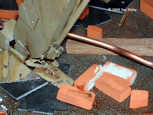
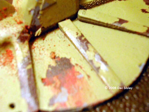
Missiles A simple task of mounting them once painted. The SPKA was ready for its engine and weapons to be mounted so the engine was fully painted up using for the most part Tamiya Smoke over Humbrol enamel “Silver Fox” which gave a nice effect. The green hose that was so difficult to glue actually took paint well. Before mounting in place Oils where used to dirty the engine housing area using black and burnt umber. “Araldite” two part epoxy resin made sure the engine was going nowhere. The missile launcher box is pushed into the engine top so as to turn freely and it can still move up and down as the mount I made months ago fitted over the raised lugs of the computer component. Paint and Markings Time to move back to painting. The body had not been stuck to the legs, which are still free to come out of the base. As seen the basic camouflage scheme was in place but the parts need weathering down before finally being fixed together so as to reach all the nooks and crannies. A dry brush with oils, washes with enamels and thinners and a wet pinpoint brush showed wear and tear. For the extra wear on the feet dark brown was applied randomly. When dry silver was painted onto raised areas and left to dry too. Using a ripped up piece of scouring pad I dabbed some masking fluid over the feet trying to hit only the brown and silver but not worrying if grey primer was also masked. Next a bright Orange-Tan was painted over the masking fluid so as to be localised to the all ready painted areas. This was left only to dry off to the touch but not fully cure and then also covered in random dabs of masking fluid before being sprayed Sand colour immediately the masking fluid had set. Once the spray was dry after a few hours I rubbed off the mask, which had prevented the Orange-Tan enamel from setting fully. I rubbed always down wards to mimic the flow of rainwater and this drew the Orange colour with it giving a nice varied rust effect. I then added brick dust.
Trying to produce decals from my printer didn't go as planned so the decals came from a Revell 1/32 scale Bf 109 and used a pair of number 2's. Once the decal was applied on the sides of the belly I assembled the body onto the legs with a good amount of glue. Unfortunately the glue worked in sticking the gaiters and legs to the axel mount but the body remained free, which because of its weight tipped forward. After trying to get superglue into the joint with out success I drilled out the side of the mounting point and trickled super glue in from the side. This worked so I then filled and carefully sanded down the access hole. The feet were glued to the base aligned with the legs but also mounted on top of rubble to give it some “weight”. This was necessary for the toes to be placed correctly later and ensuring the rubble didn't look added around the vehicle but was part of the scene. The rear facing toes had been left for a while with different ideas for linkage but in the end I settled for a simple design, using shaped tail ailerons and sports car suspension parts. Once in place these gave the KROTE look that I was after. Taking more references from the GUSTAV I needed to have some shoulder plates above the arms, this would also disguise the rather thin sockets that the arm had were they met the body. M60 front track fenders were suitably curved and provided the best solution. I had tried heat forming with a spoon but that had been a disaster. The track fenders were all slightly damaged so after I'd made a paper template to the desired shape I kept modifying it till the curves fitted the remaining areas of the best two fenders and then cut these out. Some holes required filling and sprues added for attachment lugs underneath with detail on top. To help focus me I gathered together the last parts and bagged them up, away from the jumble of sprues and remaining bits in the box. It was then simply a case of working my way through the parts. Weapon Targeting Lens This was to be the area on the belly that had originally been the hole in the front of a disposable camera. I painted it red with a dot of white as a high light. Unfortunately when I placed the camera lens over the area it magnified the painted area and the red with high light did not look anything more than brush strokes. I removed the lens and dug out some decals from the large scale Me109 I'd already been using. Cockpit dials and some data labels were placed onto the red background. These are great, and being nicely detailed are more visible when viewed behind the magnifying lens. The lens was retained by another part from the disposable camera, saving glue being needed on the lens itself. Final Cockpit Glazing
As detailed before, the glazing had been cut carefully from a rigid clear container. I had got one part that conformed almost perfectly to the rear of the head area and a slim piece that while not shaped correctly to fit, did have the right profile to stick against the base of the hatch. This was perfect as it matched the back box image from the SF3D GUSTAV that had been the guide for much of this build. All that was missing was a piece to bridge the gap between front and back. I had to go for a bluff as no parts of my clear plastic matched the curve of the cockpit. I rounded of the front of a suitable piece and then placed it as if retracted into the cockpit, once again mimicking the GUSTAV. The slim clear part at the lower front had a small crack so I decided to hid that as best I could with a windscreen wiper. The glazed parts were all given a good clean to remove adhesive from the tape that protected them when being cut. I used for the first time Humbrol “Clear cote” to give it a more glass like finish and hide some of the scratches. This is a nice product and improved the glazing. Side Protection Bars Once again a detail seen on the GUSTAV. These were added from a kit piece that was heated and slightly stretched at the middle and then bent to give the required length and shape at the ends. (the part was just too short untreated) White PVA was used to restore correct thickness and superglue to attach to the body.
Rear Light Lenses and Starting Handle This was a humours touch using a part from the M60's hull, giving the model more of that retro-German feel by mimicking the trucks used by the Wermacht in Russia commonly seen in the winter with the starting handle left sticking out the front of the engine. Angled as if swinging with the walking movement of the SPKA, the final piece was now added. For the rear lights “Micro Crystal Clear” over painted recesses worked well.
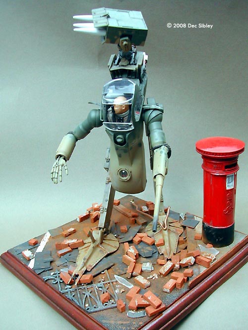
Final Touches The rest of the decals were added from the large ME109 sheet and the base dusted with brick dust and powders with more dolls house bricks added as well as a British Post Box (Pillar Box) once again a dolls house accessory which I ground out with a burr and detailed up before repainting and weathering. I was so happy with my build I broke the forum build rules when it came to basing it by adding a diorama setting.
Conclusion Done. ... and what an enjoyable task it was. I really liked the constraints and use of imagination that the BOX OF STUFF build forced on me. Also my confidence in scratch building increased 100%, as this is my first total scratch built model. At times the lack of progress was frustrating but that happens with any model. |